
【Industry Application】Precision Measurement of Worm Gears Based on Laser Displacement Sensors
Nov 21, 2023
Abstract: Based on the characteristics of existing worm gear measurement technology, a non-contact measuring method for worm gears based on laser displacement sensors and corresponding tooth profile shape and pitch deviation algorithms are proposed. A comprehensive measurement device is constructed to realize non-contact data acquisition. Through comparative analysis with smooth curves fitted by sampling points from ideal tooth profiles models, the tooth profile shapes and pitch deviations can be obtained. This method simplifies the measurement process of worm gears and improves measurement accuracy and efficiency.
Keywords: Worm Gear Measurement Laser Displacement Sensor Deviation Analysis Non-Contact Measurement
Introduction
The worm wheel as an important part of worm gearing has different requirements for its parameters and precision levels according to application scenarios. In order to ensure the transmission accuracy, working stability, and reliability of worm gearing in each application scenario, it must detect the geometric accuracy of worm wheels and worms. For worm gearing used as a rotary center divider, strict control over the cumulative error of the pitch of the worm wheel is required to ensure the accuracy of division motion; for worm gearing, strict control over the axial pitch accumulation error of the worm and the limit tolerance of the pitch of the worm wheel is needed to ensure the smoothness of the worm gearing; for reliable meshing movement between the worm and the worm wheel, strict guarantee of the accuracy of the tooth profile and surface of the meshing direction is necessary.
At present, CNC coordinate measurement and the overall error detection of worm wheels are widely applied methods for worm gear inspection. However, this type of measurement requires planning the corresponding probe path before measurement according to the tooth profile shape of the measured parts, which uses complex instruments and methods that have low generality and take longer time. The paper utilizes the laser displacement sensor to measure the relative displacements of the axial tooth profile points of the worm and specific end face tooth profile points of the worm wheel at their respective positions along the tooth profile to construct the measurement model, thereby analyzing and calculating out the tooth profile shape errors, pitch errors, and tooth profile shape errors, and axial pitch errors of the worm wheel. Using non-contact measurement techniques avoids the need for path planning against different worm gears, does not directly contact the measurement surface, eliminates the need for probe radius compensation, simplifies the pre-measurement steps, thus effectively improving measurement accuracy and efficiency.
1 Design of the Overall Structure of the Measuring Device
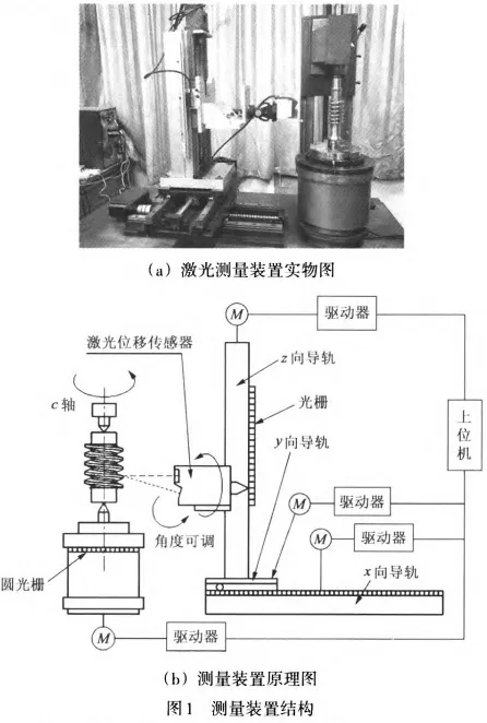
To achieve non-contact measurements of worm gears, the designed measuring device should be able to perform movements including one rotational axis and three linear axes. The structure diagram of the measuring device is shown in Figure 1. It belongs to a vertical structure composed mainly of x, y, z three linear sliding guides perpendicular to each other, c-axis rotation platform, and space pose arbitrarily adjustable laser displacement sensor system. Among them, the x, y, and z three linear slides are arranged perpendicularly, the base of the x-axis slide is fixedly connected to the workbench of the measuring device, the base of the y-axis slide is fixedly connected to the slider of the x-axis slide, the base of the z-axis slide is fixedly connected to the slider of the y-axis slide, and the bottom plate of the laser displacement sensor system is fixedly connected to the slider of the z-axis slide. C-axis refers to the rotating axis around the central axis of the measuring device's rotation platform. Each moving or rotating direction is equipped with high-precision grating scales. By programming multiple-axis control cards, various directions' motions can be controlled.
1.2 Non-contact laser measurement method for worm gears
The working principle of this measuring device is based on coordinate value measurements, where a servo system drives the movement mechanism carrying the laser displacement sensor to complete data collection from the gear profile of the worm wheel and worm shaft. According to the relative distance between the measured point and the laser displacement sensor as well as the relationship between the probe head and the machine tool coordinate system, coordinates are calculated for the gear profile of the worm wheel and worm shaft, which can then be analyzed by computer calculations to obtain deviations in tooth shape, pitch deviation, and tooth shape deviation, axial pitch deviation.
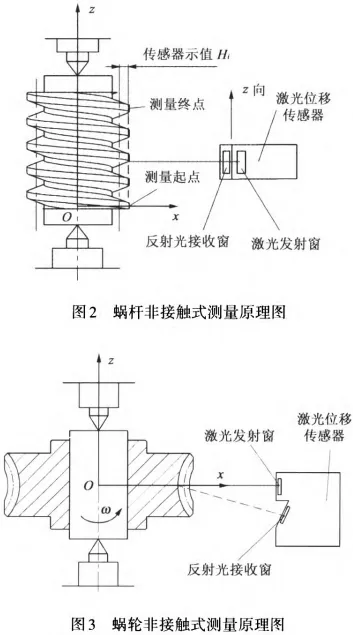
The non-contact measurement principle diagram of the worm shaft is shown in Figure 2. The sensor was moved to the radius position of the worm shaft division circle, controlled z-axis guide rail slide table motion, so that the measurement light spot projected onto some top of teeth at the measured axis section of the worm shaft being tested as the starting position of measurement, and executed calibration commands for the measurement coordinate system. Z-axis guide rails were uniformly accelerated up with an average speed of 0.16mm/s, while the system recorded the data collected by the sensor and the position data fed back by the z-axis grating, totaling three full teeth.
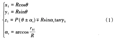
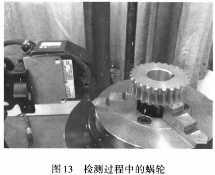
The non-contact measurement principle diagram of the worm wheel is shown in Figure 3. The sensor was moved near the middle end surface of the worm wheel, making its light spot coincide with the middle end surface; adjust the sensor attitude to ensure it is vertical and within the range of the entire tooth height; open the measurement system, causing the rotary stage to rotate evenly at a constant speed of 0.64 (°)/s for one week, automatically recording relevant data and performing error analysis.
2 Establishment of the Ideal Model for Worm and Worm Wheel
To achieve precise measurement and error analysis of the worm and worm wheel, it is necessary to establish corresponding tooth surface equations based on the principle of tooth surface formation of the worm and worm wheel. The research team, based on the review of relevant literature and knowledge of solid geometry and coordinate transformation, has studied in detail the principle of formation of the gear tooth surface and established the ideal profile model of the worm and worm wheel.
2.1 Tooth Surface and Profile Equations of ZI Worm
2.1.1 Tooth Surface Equation of ZI Worm
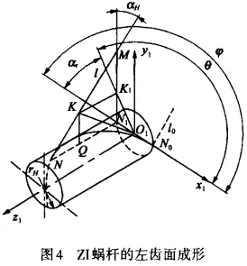
According to the principle of tooth surface formation of the ZI worm, the tooth surface forming line of the ZI worm is tangent to the base cylinder and forms an angle Yb with the end plane. Figure 4 shows the forming process of the left tooth surface of a right-handed ZI worm. Suppose the initial position N0 of the tangent point of the tooth surface forming line with the base cylinder is on the X1 axis. When the forming line rotates around the Z1 axis in a spiral motion through an angle α, the tangent point moves from N0 to N, and NN1=Pα. Taking any moving point K on the forming line, the coordinates x1y1z1 of point K can be calculated based on the geometric relationship in Figure 4. Therefore, the tooth surface equation of the ZI worm can be expressed as:
In the equation, R represents the radius vector of the moving point K on the gear surface; θ is the dynamic parameter angle; P is the helical parameter of the worm; yb and yb1 are the lead angle and the base cylinder radius of the worm's base cylinder, respectively. The "-" sign in the equation indicates the left gear surface, while the "+" sign indicates the right gear surface. By reversing the sign of the helical parameter P, the gear surface equation for a left-handed ZI worm can be obtained.
2.1.2 The tooth profile equation of zI worm gear
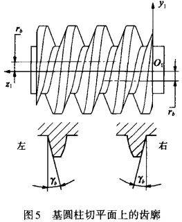
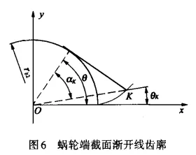
By knowing that the contact line between the tooth surface and base circular cylinder is tangent to the base circular cylinder, it can be known that in a plane perpendicular to the base circular cylinder, the tooth profile of zI worm gear is a straight line with an angle yb from end face. As shown in Figure 5, for right-handed zI worm gears, on the cutting plane at y1 = rb1, the left side tooth profile is linear; while on the cutting plane at y1 = -rb1, the right side tooth profile is also linear. For left-handed worm gears, this relationship is reversed.
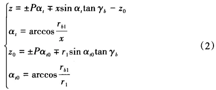
By setting y1 = 0 in Equation (1), we can obtain the axial tooth profile equation of a right-handed zI worm as follows.
2.2 General equation of worm wheel's tooth surface
According to the general equation of the worm gear's tooth surface, it can be known that ZN, ZA and ZI have a parallel section with axis line in which the tooth profile is straight line. And at this section, the meshing transmission between the tooth profiles of the worm gear and the worm wheel can be regarded as rack-and-pinion transmission. Therefore, the error analysis of the meshing transmission needs to establish an ideal involute tooth profile on the corresponding end section.
In Figure 6, the involute tooth profile equation is
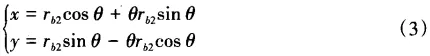
where θ represents the pressure angle parameter; αk represents the pressure angle; θk represents the direction angle; rb2 represents the base circle radius of the worm wheel's involute tooth profile. In the range from the root angle θf2 to the top angle, given equal intervals of the expansion angles will allow us to calculate all coordinates of points on the involute tooth profile. Among them,
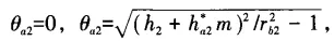
where r2 represents the diameter of the worm wheel's pitch circle; m represents the module; h*a2 represents the height coefficient of the worm wheel's tooth tip; rb2 represents the base circle radius of the worm wheel's involute tooth profile.
3 Worm wheel-worm gear deviation analysis method
3.1 Mathematical compensation for installation eccentricity
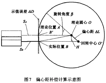
When the worm wheel is installed by three-jaw chuck on the rotary table, there inevitably exists installation eccentricity causing measurement errors. To reduce the error caused by the eccentric distance, we need to compensate the measured data. According to the principle of laser displacement sensor, the installation eccentric distance can easily be measured and compensated. The relationship among the measured value D, standard measuring range L and the distance S between the point where the laser beam emitted by the sensor reaches the sample is expressed as

When the radius of R is r, if the worm wheel rotates β degrees around the center of rotation, then the theoretical position of A point is obtained when B point is actually measured due to the existence of installation eccentricity. The radius of RA is RDa, RD is the function of the sensor reading. Based on plane geometry relations and △BB'O, the following equations are derived:
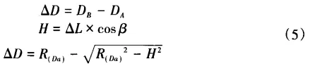
Since R(Da)=R(Db-△D), the value of ∆D must be calculated first. Thus, nested solution methods should be used here. After substituting R(Db) into Equation (5), the first calculation of ∆D was performed. Then, according to the calculated ∆D, DA was substituted back into Equation (5) again to re-calculate ∆D. This process continues until ∆D becomes stable, indicating that the calculated DA has been corrected after the installation eccentricity compensation using the laser displacement sensor.
3.2 Worm gear deviation analysis method
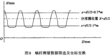
The laser displacement sensor measures each data point corresponding to one grating position. In order to exclude the interference of scattered light rays generated by the contact between the zI worm gear's tooth bottom smooth transition tooth profile and the laser beam, as well as non-standardized issues such as tooth corners, etc., affecting the accuracy of the error analysis results, the error analysis interval selected is the radial height range outside 0.7 modules to inside 1 module of the divisional circle, as shown in Figure 8.
After coordinate transformation and data screening, the k sampling points Pi of the worm gear's axial tooth profile on one side were fitted out based on the least squares method of cubic polynomial fitting. The total sum of squared deviations δi2 of these k sampling points to the fitted curve can be expressed as
By taking the derivative of ai on both sides of the above formula, simplifying through algebraic manipulation, we get the matrix form of the equation group below.
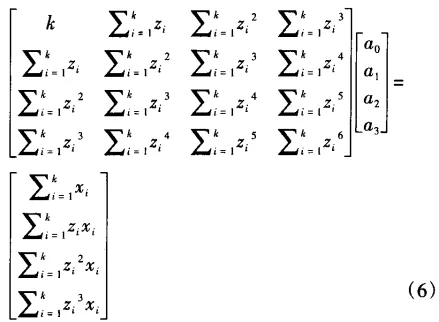
Through matrix Vandermonde simplification, we can obtain the coefficients matrix A=[a0,a1,a2,a3], thus obtaining the expression of the fitted curve.
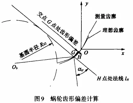
As shown in Figure 9, the ideal axial tooth profile of the worm gear is established in the analysis coordinate system xOz, which is composed of the third-order polynomial fitting curve f(z) and the axial tooth profile equation (2) of the worm gear. As the reference object for the tooth shape deviation analysis of the worm gear.
3.2.1 Tooth shape deviation calculation of the worm gear
Differentiate the tooth profile equation (2) with respect to z, and you can derive that the slope of the tangent line on both sides of the worm gear is k'.
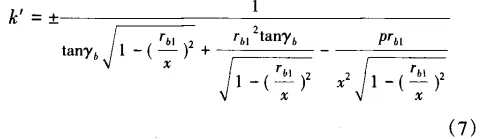
In the equation, the "+" sign on the left represents the left tooth profile, and the "-" sign represents the right tooth profile. The selected data points with equidistant x-coordinates are taken at each ideal tooth profile point Hi(zi,xi), and the normal to the profile at these points is sequentially intersected with the tiny line segments formed by the two closest tooth profile sampling data points to that normal, resulting in the intersection points Gi(z,x).
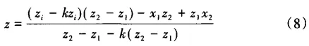
In this formula, z1 and z2 are the abscissa of sampling data points on both ends of a small straight line segment; k is the slope of the normal (k = -1/k'). According to the definition of gear profile deviation for worm gears, we can take the distance between point Gi and its corresponding ideal tooth profile as the shape deviation ffα1i at that intersection point. That is:

In this formula, z1 and z2 are the abscissa of sampling data points on both ends of a small straight line segment; k is the slope of the normal (k = -1/k'). According to the definition of gear profile deviation for worm gears, we can take the distance between point Gi and its corresponding ideal tooth profile as the shape deviation ffα1i at that intersection point. That is

In this formula, when the coordinates of intersection point Gi are higher than the ideal profile, ffα1i is positive; otherwise it's negative. If there are k intersections for a single side tooth profile and n teeth have been measured, then if we're currently analyzing the jth tooth profile, the shape deviation of that tooth profile can be expressed as

Finally, the deviation of the worm's tooth profile shape is obtained as:

3.2.2 Axial pitch deviation of worm gear
According to the three least squares method described when analyzing profile error, fit a curve with actual measured data points on the tooth profile and calculate the coordinates Ci (zi, xi) at the intersection point between this curve and the division line of the worm gear axis section. Calculate the z-coordinate interval length between adjacent teeth profiles as Px for each Ci point and compare it with nominal pitch Px0. The difference is the axial pitch deviation of the worm gear, which can be calculated by:
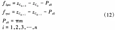
In the formula, △fLpxi, fRpxi are respectively the left-right axial pitch deviations of the tested worm gear; m is the module of the tested worm gear; n is the number of complete tooth profiles being measured.
3.3 Analysis Method of Worm Wheel Deviation
When measuring the worm wheel, laser displacement sensors collect the tooth profile data from its given end surface. According to the angle position corresponding to each sampling point Ni (Hi, θi), convert the measurement sample points' data according to equation (13) into the Cartesian coordinate system xOy's circular arc tooth profile points Pi (xi, yi).
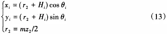
In the formula, r2 is the radius of the division circle of the tested worm wheel; m is the module; z2 is the number of teeth in the worm wheel; Hi is the sensor reading value of the sampling point location; θi is the C-axis angular coordinate value of the sampling point location.
To eliminate the negative impact caused by the base circle of involute tooth profile greater than root circle and non-standard shape of bottom part due to chamfering of top circle, select radial height range outside 0.7 modules to inside one module of the division circle. The tooth profile deviation of the worm wheel refers to the distance between two designed tooth profile traces that enclose the actual tooth trace within the calculation range of the given tooth profile. The so-called given tooth profile means the end face of the worm wheel where the tooth profile is an involute, i.e., the middle end face of the ZA worm pair mating worm wheel.
3.3.1 Calculation of Tooth Profile Deviation
First, draw the measured tooth profile based on the measurement data, then superimpose it on the ideal tooth profile through coordinate transformation, and use the distance between the two in the normal direction of the ideal tooth profile as the criterion for judging the shape deviation of the worm gear tooth profile. As shown in Figure 9, the angle between the normal line lH at any point H on the ideal tooth profile and the radius vector ObH is π/2+αH. Also, due to the property that the normal line at any point on the involute is tangent to the base circle, the normal equation at any point Hi(xi,yi) on the transformed involute tooth profile can be obtained after the position transformation.
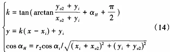
In the formula, α1 is the pressure angle of the gear profile at the pitch circle of the measured worm gear; r2 is the pitch circle radius of the measured worm gear; (xo2, yo2) are the coordinates of the intersection of the ideal gear profile and the pitch circle before the position transformation.
In the formula, α1 is the pressure angle of the gear profile at the pitch circle of the measured worm gear; r2 is the pitch circle radius of the measured worm gear; (xo2, yo2) are the coordinates of the intersection of the ideal gear profile and the pitch circle before the position transformation.
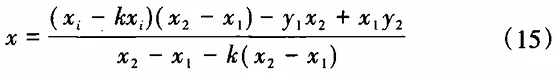
In the formula, x1 and x2 are the abscissa coordinates of the sampling data points at the ends of the small straight line segments; k is the slope of the normal, which can be calculated according to formula (14). According to the definition of the worm gear profile deviation, the profile deviation at the intersection Gi is...

If the total number of intersection points Gi of a single side profile is k, and the number of teeth of the worm gear is z2, when analyzing the j-th profile, the profile shape deviation of the j-th profile can be represented as

Finally, the deviation of the worm gear profile shape is obtained as:
3.3.2 Worm Gear Pitch Deviation
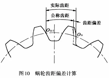
The pitch deviation of a worm gear refers to the difference between the actual pitch at the indexing circle on the tooth profile in the measured end section and the nominal pitch. As shown in Figure 10, using the previously mentioned 3-pass least squares fitting method, the coordinates O1i (xo1i, yo1i) of all the same-side measured tooth profiles' fitting lines at the indexing circle position within the intermediate end section are determined. By taking the arc length between adjacent O1 points as the pitch of the measured tooth profile and comparing it with the standard pitch, the pitch deviation of the worm gear can be obtained. The arc length between points O1i-1 and O1i can be expressed as
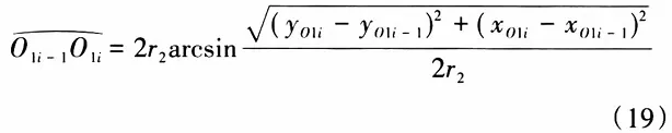
In the formula, r2 is the pitch circle radius of the measured worm wheel. Also, because the standard tooth pitch of the worm wheel can be represented as P0 = πm. From this, the tooth pitch deviation of the worm wheel at the point Oi-1Oi can be obtained.

4 Worm and Worm Wheel Measurement Experiment
4.1 Worm Measurement
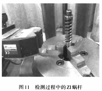
In the experiment, the zI worm used for the transmission of the mechanical EPS system in vehicles was measured. The parameters of the measured zI worm are: IT6 level precision, right-handed, module 2, two starts, normal pressure angle 20 degrees, pitch diameter 11 mm. Three complete tooth profiles were measured, as shown in Figure 11.
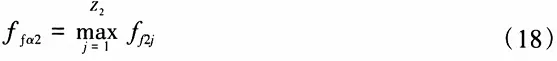
Through the computer error analysis module shown in Figure 12, the individual axial tooth pitch deviation, total axial tooth pitch deviation, and total profile shape deviation of the worm gear are obtained.
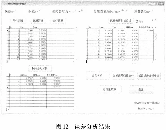
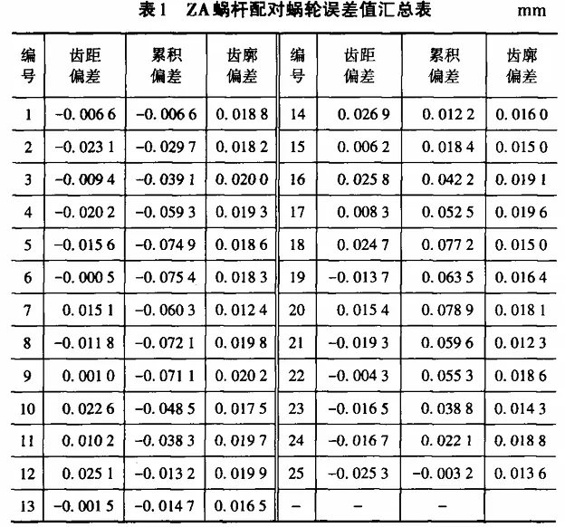
The single axial pitch deviation is max△fpx=0.0027 mm, min△fpx=-0.0065 mm, and the axial pitch deviation is fpx=-0.0067 mm. The total profile deviation is Ffα1=0.0155 mm. According to GB/T 10089--2018, the precision of the zI worm is IT6, and the error analysis results are consistent with its manufacturing precision. 4.2 Worm Wheel Measurement For the worm wheel paired with the ZA worm, the measured parameters of the worm wheel are: IT9 level precision, module 2.5, 25 teeth, the pressure angle at the middle end face pitch circle position is 20 degrees, as shown in Figure 13. Similarly, through the computer error analysis module, the single tooth pitch deviation, cumulative total pitch deviation, and total profile deviation of the worm wheel can be obtained, as shown in Table 1.
Single pitch deviation is

Total cumulative pitch deviation is
Total deviation of the tooth profile is
Total deviation of the tooth profile is
5 Conclusion
A non-contact measurement method for worm gears based on laser displacement sensors is proposed, and a worm gear measurement device is constructed, which can achieve automatic measurement of worm gears. An error analysis method is proposed that compares the ideal tooth profile with the smooth curve fitted from the collected data, which can accurately and efficiently analyze the tooth profile shape deviation and axial pitch deviation of worm gears. The time required to measure one worm using this method is about 1/3 of the time required for CNC coordinate measurement, greatly improving the measurement efficiency of worm gears. At the same time, this method and device can also be used for the measurement of other cylindrical worms and complex spiral surface parts.
Authors of this article: Zi Hao, Peng Yun, Chu Yuegang, Shen Yuhan, Song Aiping (School of Mechanical Engineering, Yangzhou University).


Recent Posts


Contact US
Product Information
Quantity
Unit
Piece
Support order samples, customization, wholesale direct, and complete payment. If the product you look for does not have corresponding customized content, pls fill out the form below to contact us, and we will reply ASAP.