
【Industry Application】Intelligent Sensing | Position Measurement of Wind Tunnel Models Based on Laser Displacement Sensors
Nov 21, 2023
Introduction
The two-dimensional measurement of airfoil profiles during wind tunnel tests is a key technology for model prediction in numerous aerodynamic applications. In these tests, it is generally necessary to measure the forces and pitching moments on the airfoil at different wind angles (attack angles). Small changes in the attack angle can cause significant variations in forces and moments, hence precise measurement of the attack angle is a major technical requirement in such tests. This study employed multiple laser displacement sensors in the wind tunnel, calculating the model's position precisely by measuring the distance between the wind tunnel wall and the wing. The measurement results demonstrated that this technology can detect model deformations and deflections that were previously unobtainable, thereby providing more accurate attack angle measurements.
Background
Wind tunnel test results are typically used to validate numerical models, and the measured two-dimensional coefficients of force and torque can be further used to deduce the forces and moments on engines or wings. In aerodynamics, the forces and moments are very sensitive to the model's geometric shape and attack angle parameters; a 1-degree change in attack angle can cause an 11% change in lift coefficient, which means that precise measurement of the attack angle is crucial in the measurement of wind tunnel models of wings.
Typical measurement schemes use magnetic encoders mounted on the wing's swivel table, but the resolution of magnetic encoders is low. For example, in this study, the attack angle bias caused by the formation of a 6000N lift and a 500Nm pitching moment could not be resolved by the magnetic encoder. Additionally, the nonlinear deflection in the spanwise direction caused by twisting and bending also affects the measurement, making it impossible to determine the specific aerodynamic state.
Introducing acceleration sensors into the wind tunnel model can solve this problem. The integral of the acceleration sensor's output reflects the displacement and direction of the model. By continuously recording multiple acceleration sensors, the displacement and direction of multiple points on the model can be tracked. In addition, there are measurement techniques that use camera tracking of marked points for post-processing to obtain measurements of model deflection and deformation, as well as schemes that use laser interferometers to track the position of the model, but both of these technologies have drawbacks of complexity and high cost.
Innovation
The work in this paper employs laser triangulation displacement sensors to measure the distance between the model and the wind tunnel wall. This scheme uses commercial products with high-precision absolute distance measurement capabilities and does not interfere with other wind tunnel measurement equipment.
Technology
The wind tunnel test section in this article is a rectangular area measuring 7.3m in length and 1.85m by 1.85m in cross-section, with walls made of solid aluminum plates. The wing used is a 0.8m long DU96-W-180 wing, and the angle of the wing's control surface turntable is measured using a Renishaw LM10 linear magnetic encoder. A typical test procedure involves rotating the control surface turntable to a specific angle and locking it, then activating the wind tunnel for 3-4 seconds, after which pressure sensors at 90 points are installed to measure air pressure. The air pressure data can be used to calculate the wing's lift coefficient and torque coefficient. Four laser displacement sensors are mounted at independent positions in the wind tunnel, as shown in Figure 1.
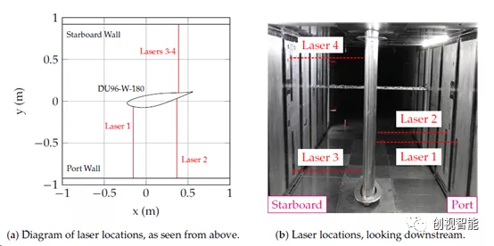
Figure 1 Installation diagram of the wing and laser displacement sensors in the wind tunnel model
During use, the temperature drift error of the laser displacement sensors is compensated by linear regression, as shown in Figure 2. At the same time, with the wind tunnel air intake closed, the wing is rotated stepwise between ±16 degrees of attack angle, and the calibration is completed by recording the angle data and the data from the four lasers, as shown in Figure 3. The displacement measured by the laser and the angle of rotation have a mapping relationship, and the uncertainty of the mapping is also given at the bottom of the figure.
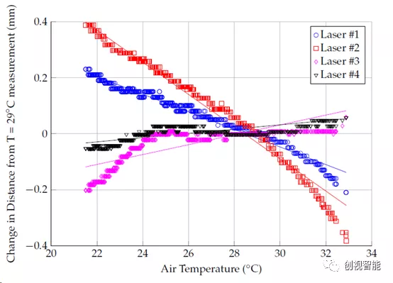
Figure 2 emperature drift curve of the laser displacement sensor
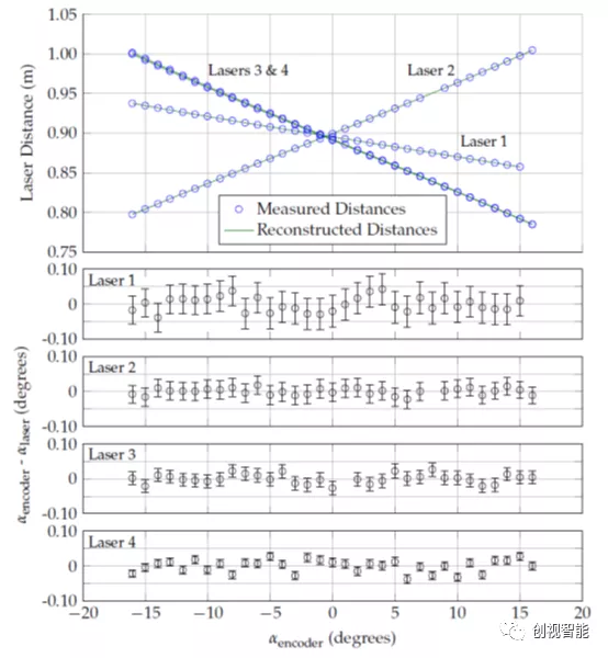
Figure 3 Calibration curve between the laser displacement sensor and the rotation angle
Next is the actual experimental measurement phase where the wind tunnel is opened. The inconsistency between the data obtained by the laser displacement sensor and the rudder turntable angle represents the deflection and deformation generated by the wing. For specific analysis, please refer to the original text. In summary, this measurement scheme based on laser displacement sensors can measure wing model deflections of less than 0.15 and deformations of less than 2mm, which is more practical and operable compared to other measurement schemes.
Keywords: Laser Displacement Sensor; Wind Tunnel Test; CMOS Line Array Camera
References:
Kuester M, Intaratep N, Borgoltz A.LaserDisplacement Sensors for Wind Tunnel Model Position Measurements.Sensors(Basel). 2018 Nov 22;18(12):4085. doi: 10.3390/s18124085. PMID:30469493;PMCID: PMC6308610.


Recent Posts


Contact US
Product Information
Quantity
Unit
Piece
Support order samples, customization, wholesale direct, and complete payment. If the product you look for does not have corresponding customized content, pls fill out the form below to contact us, and we will reply ASAP.