
【Industry Application】Application of Laser Sensor to Measure Rim Dimensions
Nov 29, 2023
Abstract: This paper introduces the general situation of rim geometric parameter measurement in China and abroad, gives a scheme for scanning measurement with laser displacement sensors on wheel rims, and conducts experimental research.
Currently, on freight car wheelsets, fourth-generation inspectioners are used to measure rim parameters; special measuring tools are used to detect wheel diameter and inner distance between wheels. When measuring, results are first noted on the wheelset using chalk, then copied onto card No. 51C, finally manually entered into microcomputers. The method involves many intermediate links, resulting in large human errors during measurements. With train speeds increasing, wear on wheel flanges and edges is becoming more severe, so it's very important to accurately test the geometric parameters of wheelsets in time.
1 Automatic Measurement Method Overview of Wheelset Geometric Parameters
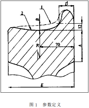
The definition of rim shape parameters is shown in Figure 1: Curve 1 represents the original contour line of the rim, while curve 2 represents one form of worn-out contour lines. The thickness of the rim is defined as A, the wear of the wheel tread is B, the diameter of the wheel is C, the thickness of the edge is D, and the width of the rim is E. Among them, the most critical factor is also the hardest to measure - the thickness of the edge D. In actual measurements, these parameters are determined by averaging three intervals of cross-sectional data.
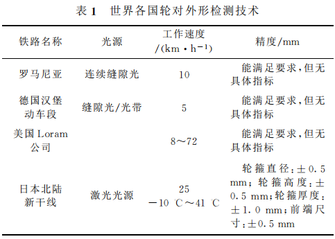
For automatic measurement of wheelset geometric parameters, devices developed by rail transportation advanced countries mainly use ultrasonic technology or charge-coupled device (CCD) technology. Russia adopted ultrasonic measurement methods around 1995, successfully developing an automated detection device that can run at no faster than 5 km/h. Sensors were installed to measure each characteristic surface of the wheel, after processing, the measured values had a wheel diameter error not exceeding 1 mm, an edge thickness error not exceeding 0.5 mm, and a tread wear error not exceeding 0.30 mm. Other countries all adopt CCD technology for automatic testing of wheelset external dimensions, summarized as Table 1.
In recent decades, China has also conducted studies on wheel tread inspections, achieving some partial results such as new types of wheelset exterior measurement instruments, parameters of wheelset wear, linear array CCD detectors for wheelset outer shapes, and linear-array-matrix-measuring CCDs. Literature analyzed and compared contact-type, CCD, and laser sensor schemes, selecting the latter two technologies to develop wheelset automatic detection equipment, giving accuracy levels of: rim thickness, rim width, axle diameter of wheelbase, inner distance between wheelsets, tread wear precision of 0.1 mm, rim thickness precision of 1 mm. However, this device structure was complex and costly, additionally, the light source of the linear-array CCD could not be calibrated beforehand, making system debugging difficult. The literature believed that the cost of the laser sensor scheme was higher than CCD, if multi-point direct measurement was adopted, approximately ten sensors would be needed, indeed true. But if adopting scan measurement, even considering measurement time factors, only two lasersensors would be required, greatly reducing costs. Due to few examples of laser sensors being used for scan measurement, we carried out experimental research here.
2 Laser Displacement Sensor Scanning Measurement Scheme
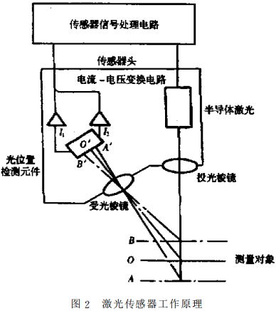
Laser displacement sensor working principle is shown in Figure 2. Light beams emitted from semiconductor laser sources are focused into points by concave prisms, reflected off the object under test, part of which reflects back to the receiving prism where they focus again on position detecting elements. As the object moves from O point to A or B, the position detecting element will move correspondingly from O' point to A' or B'. By calculating the position of the detected light spot on the position detecting element, the displacement amount of the tested object can be obtained. Since the optical system uses high-precision non-spherical prisms, and the circuit has a function of linearization, therefore, output voltage proportional to distance can be achieved, providing highly reliable detection systems.
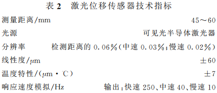
Experimental tests employed laser displacement sensors with technical specifications listed in Table 2.
The sensor error caused by a 10°C change in ambient temperature is:

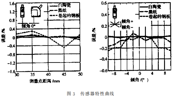
The linear characteristics of sensor output are shown in Figure 3. From the figure, it can be seen that the maximum errors caused by the local non-perpendicularity between the measured light and the tested point as well as the linearity of the sensor are respectively:
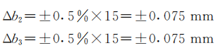
Therefore, in the experiment, the total error of the sensor is as follows:

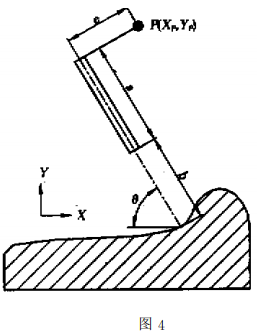
Based on the characteristics of the laser sensor mentioned above, the rim scanning measurement scheme constructed is as follows: A high-precision servo control system is used to adjust the direction of the sensor, making the emitted light as perpendicular as possible to the surface being measured while maintaining an appropriate distance between the sensor and the surface. The measurement principle is shown in Figure 4: Point P represents the trajectory of a certain point on the sensor, point Q represents any point on the rim surface being measured, e and a represent the distances from point P to the emitted light of the sensor and the end face of the sensor, respectively, b represents the distance between the sensor and the surface being measured, and the angle between the laser sensor light and the X-axis can be derived from the triangular relationship, the coordinates of any point Q on the measured surface are:
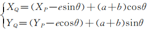
Therefore, according to template contours, determining multiple positions of P points and their corresponding azimuth angles allows moving the sensor to those locations and adjusting its orientation accordingly, obtaining other points on the rim tread. According to the definitions of wheelset geometric dimensions, parameters including rim thickness, wheel tread wear, edge thickness, and rim width can be calculated.
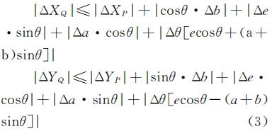
This scheme’s measurement error originates from measurement apparatus, sensors, and digitalization errors etc., according to Equation (2), coordinate value of point Q on the tested surface is affected by coordinate point P, rotation angle θ of the sensor, sensor characteristics, a and e calibration deviations. They are denoted as ΔXP, ΔYP, Δθ, Δa, Δb, and Δe, respectively. Maximum error estimation formula of coordinate value of point Q is given below:
3 Experimental Results
Experimental setup consists of a measurement head, bullhead lathe, wheelset templates, two linear arrays, and a computer equipped with counting cards and AD modules. The measurement head includes a shaft connected to the same axis, laser sensor, stepping motor, and photoelectric encoder, while the computer contains countercards and AD modules. The measurement head is fixedly mounted on the bullhead lathe’s tool post. The laser sensor can rotate, whose rotational angle is measured by the photoelectric encoder. Meanwhile, the wheelset template is fixed on the bullhead lathe platform, moved by hand via the bullhead lathe’s handle mechanism, its movement along X-Y directions recorded by the linear arrays installed on the bullhead lathe. The implementation process of the experiment included:

(1) Calibration of the laser sensor directly adopts the wheelset template as target, taking the reading of the linear array as true value, deriving relation between measured distance b and sensor voltage u as follows:
(2) The wheelset template is processed based on standard wear type tread profile, importing discrete data of the template contour line into the computer through the bullhead lathe’s handle mechanism, moving the template to predetermined location by controlling the stepper motor, rotating the sensor simultaneously to obtain other points on the contour line by equal interval measurement mode. Finally, over 300 points’ coordinate values indicate the contour line of the template tread and baseplate.
Measurement procedure involved manual movement of the template, remaining operations and treatments performed automatically by the computer: Through the counting card collecting readings from the linear arrays and photoelectric encoders, converting analog signals from the laser sensor to digital ones, performing calculations to determine plane position of the measured points, recording results.
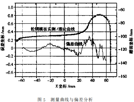
Measured results are shown in Figure 4: Point-line curves show real-time measurement results of the template model, dashed curves denote standard wear type tread profiles, solid curves represent measurement deviation curves & From figure, maximum measurement error appears near the inner side of the rim, with maximum deviation ±0.3mm, tread measurement deviation is within ±0.1mm.
According to Equation (3), analyzing measurement error: since Xp, Yp, θ are derived from the linear arrays and photoelectric encoders, due to their high precision of 5μm, can be ignored, photoreceptor encoder precision is 3.14*10-4rad, e and a length sum is about 85mm~100mm, thus, item 4th in equation does not cause greater than 0.0314mm error; sensor installation axis-to-emitting light beam distance e and axis-to-end-face distance a are measured by calipers, measurement error is 0.01mm, gap-induced error caused by sensor installation axis is 0.05mm; machining error of the wheelset template is ±0.1mm, sensor characteristics error Δb = ±0.22mm. According to Equation (3), total measurement error of the trial is:
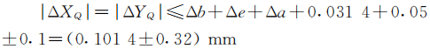
Overall analysis agrees well with theoretical calculation.
During experiments, another finding was made: color change of objects affects measurement accuracy significantly. If the object surface color approaches black, using auto-compensation functions of laser sensors may fail to receive reflection light and cannot work normally. Therefore, when measuring surfaces with significant color differences, choose laser sensors having auto-compensation functions for colors, preferably those employing photoelectric receptors as position-sensitive elements, especially laser sensors with color auto-compensation functions.
4 Conclusion
(1) Using laser displacement sensors for scanning measurement is feasible, meeting requirements for wheelset detection.
(2) For scanning measurement of maintenance line wheelsets, select laser sensors with color auto-compensation functions to reduce errors induced by surface color difference.
(3) During scanning measurement of wheelsets on repair lines, employ laser sensors with color auto-compensation functions to minimize errors induced by surface color difference.

.jpg?x-oss-process=image/resize,w_100/quality,q_100)
Recent Posts


Contact US
Product Information
Quantity
Unit
Piece
Support order samples, customization, wholesale direct, and complete payment. If the product you look for does not have corresponding customized content, pls fill out the form below to contact us, and we will reply ASAP.