
【Industry Application】Research on Conical Thread Detection Method Based on Laser Measurement
Nov 21, 2023
Abstract: As a type of connection thread with tight connection and good air-tightness, tapered thread has the advantages of easy assembly, achieving interference fit, and ensuring good sealing effect. With the improvement of its design and processing levels, higher accuracy is required for the measurement of tapered threads. Ensuring that the axis of the tapered thread is coplanar with the laser path during measurement has always been a challenge. This paper explores methods for measuring tapered threads and designs a tapered thread detection device that can accurately center the tapered thread and achieve non-contact detection using a laser. By analyzing and fitting the measurement results and comparing them with the standard profile, it is determined whether they meet the requirements. Experimental studies have proven the practicality of the device.
Keywords: Tapered thread; Centering; Non-contact; Laser measurement
Introduction
Traditional tapered thread detection methods mainly fall into two categories: contact and non-contact. Non-contact methods mainly measure the taper using optical instruments such as universal tool microscopes. The main problem with these methods is manual visual aiming, low automation, low efficiency, and the potential for eye fatigue with prolonged use. In recent years, machine vision detection technology has gradually become a hot topic in the inspection industry. Machine vision measurement methods belong to the non-contact measurement category and have the characteristics of measuring multiple geometric parameters of threads in a single measurement with high efficiency, which can greatly improve detection efficiency. However, due to the high cost, this measurement cannot be widely applied. In actual measurements, many non-contact laser measurement devices have not taken into account the asymmetry of the tapered thread structure, failing to properly address the correction issues caused by constantly changing measurement distances, resulting in inaccurate measurement results. In actual production, traditional thread detection can no longer meet the requirements for improving product quality and productivity. Importing complete sets of foreign equipment is costly. Therefore, based on the basic methods and principles of thread measurement, a tapered thread detection device has been independently developed using computer processing technology, which can achieve accurate centering, fast, and efficient measurement of the contour of the measured part, achieving high-efficiency, low-cost automated detection.
1 Structure and Principle of the Detection Device The measurement system consists of a laser probe, probe controller, tapered thread clamping device, computer, and output devices. It mainly includes three major parts: measurement, clamping centering, and adjustment.
1.1 Measurement Part The measurement part mainly includes a laser probe, stepper motor, and slider.
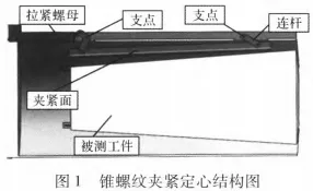
1.2 Clamping Centering Part The clamping centering part mainly consists of a tightening mechanism, tension nut, bushing, and clamping surface. Three clamping surfaces are evenly distributed on the bushing, playing a centering role in clamping the tapered thread. When the tension nut pulls the connecting rod, with the support of the fulcrum, the clamping surface can swing at a certain angle. When the swinging angle is the same as the taper of the tapered thread, the workpiece to be measured is clamped. The structure is shown in Figure 1.
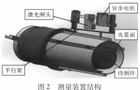
1.3 The adjustment section mainly includes a parallel frame and a vertical guide rail. The parallel frame ensures that the trajectory of the measuring head's movement is coplanar with the axis of the conical thread; the vertical guide rail is used to adjust the distance from the laser emission point of the measuring head to the contour point of the conical thread, ensuring that it is within the measuring range of the measuring head, thereby enabling the measurement of conical threads of different size ranges. The specific structure is shown in Figure 2.
2 The operating principle of the detection device
Rotate the left end tightening mechanism to pull the tension nut, which moves the connecting rod along a direction parallel to the axis of the tension nut. The connecting rod then pulls the clamping surface to clamp the workpiece being tested. The stepper motor drives the slider to move the measuring head along a direction parallel to the axis of the conical thread, collecting profile data points of the conical thread. The computer processes these data points to generate a profile chart of the conical thread and calculate its parameters. These parameters are then compared with standard values to determine if they meet the required specifications.
During the collection of thread profile points, the presence of the thread helix angle means that to ensure the measuring head's movement is perpendicular to the outer contour of the conical thread and to avoid any measurement偏差 (deviations in the data points), a parallel frame is installed between the two clamping surfaces. The parallel frame mechanism ensures that the displacement direction of the measuring head is parallel to the axis of the conical thread, thereby eliminating any inaccuracies caused by the misalignment of the measuring head position.
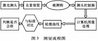
The three-claw clamping mechanism ensures that the axis of the conical thread aligns with the axis of the bushing, ensuring that the measuring head's movement trajectory is in the same plane as the thread axis, and thus ensuring the accuracy of the measured data points. Within this plane, the measuring head can move up and down along the guide rail within a certain measurement range, allowing the measurement of conical thread profiles of various sizes. This ensures the versatility of the measurement range. The measurement process is illustrated in Figure 3.
3 Data Processing
3.1 Outlier Filtering for Thread Profile Data Collection and Processing
The collection and processing of thread profile data points is crucial for the task of thread detection. In the process of data handling, the most important aspect is to obtain accurate profile points of the tapered thread. The noise reduction process can yield data points for accurate calculation. Through filtering analysis, it can be ensured that the image remains undistorted, ultimately achieving the detection of thread geometric parameters. Since outliers have the greatest impact on experiments, the method of outlier filtering is used to filter the data. In addition to manually removing data points, the 3σ criterion can be used to eliminate suspected offset regions. The formula for calculating the variance σ is as follows:
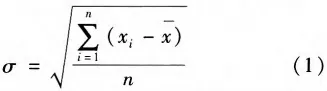
Calculate the maximum value of the residual di = xi - x, denoted as l di I max. According to the 3σ criterion, if I di I max > 3σ, then the measurement point is an offset measurement point and should be removed. The processed data is recalculated, and the calculation process is repeated until I di I max < 3σ.
3.2 Data Fitting
There are many methods for data fitting. Experimental results show that the weighted total least squares method has better plane fitting effects on point cloud data. After outlier data filtering, the data points of the contour are obtained, and the least squares method is used to fit the data. The fitted contour curves are shown in Figures 4 and 5.
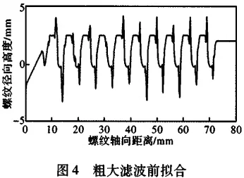
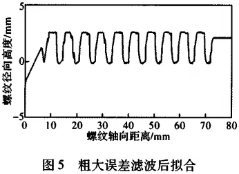
By conducting multiple measurements and calculations on the suspected contour diagrams, the calculated taper thread parameters are compared with the standard parameters to determine whether the measured part meets the standards.
4 Conclusion
There are many methods for detecting taper threads. The method discussed in this paper can reduce the error caused by the misalignment of the thread axis and the measuring axis during installation and positioning. This device can measure taper threads of different sizes, making it more versatile. The measurement process is simple and convenient, meeting the requirements in practical applications. While saving costs, it ensures high-precision measurements and has value for widespread use.


Recent Posts


Contact US
Product Information
Quantity
Unit
Piece
Support order samples, customization, wholesale direct, and complete payment. If the product you look for does not have corresponding customized content, pls fill out the form below to contact us, and we will reply ASAP.