
【Industry Application】Measurement Technology for the Thickness of Self-Supporting Metal Ultrathin Films
Jan 12, 2024
Abstract: This paper introduces the principle of surface optical positioning using white light spectral confocal and the self-supporting metal film thickness measurement system with coaxial conjugate symmetry. Through measurement experiments on standard step heights and standard block thicknesses, as well as analysis of the measurement result uncertainties, the accuracy and reliability of the film thickness measurement system are verified. Within the thickness range of 300μm, the system's relative measurement uncertainty reaches 0.99%, meeting the technical requirements for high-precision measurement and traceability of film thickness. Keywords: Metrology; Self-supporting film; Spectral confocal; Film thickness.
1 Introduction
In recent years, with the rapid development of semiconductor, electronics, communications, and computer technologies in China, the control of surface coating quality has received increasing attention. Particularly, the thickness and uniformity of metal coatings directly affect the working performance, stability, reliability, and lifespan of the final products. In x-ray fluorescence coating thickness measurement and analysis systems, metal films with thicknesses less than 100μm are often used as thickness standard pieces to simulate metal coating thickness for calibrating the measurement accuracy of the system. They are the only standard and the most critical parameter in the transfer of coating values. In length measurement, conventional methods for measuring the thickness of thin sheets involve using contact sensors or measuring instruments to target and measure the sample from one or both sides. The disadvantage of this contact method is that the measurement force acts directly on the sample surface, causing deformation and damage to the sample, making it unsuitable for measuring the thickness of flexible and ultra-thin samples. Therefore, for the measurement of metal films with thicknesses less than 100μm, non-contact methods must be explored. With the development of optoelectronic detection and analysis technology, in recent years, measurement technologies based on white light spectral confocal and spectral analysis have emerged, featuring high-precision non-contact positioning. They have been recommended as measurement methods for surface structural characteristic parameters in ISO 25178, suitable for non-destructive measurements of surface microstructures, soft materials, and ultra-thin film thicknesses. By double-sided positioning, they can be applied to the measurement of absolute thickness of metal films.
2 The technical principle of the white light confocal sensor
As shown in Figure 1, the white point light source W passes through the beam splitter B and the confocal lens L, converging near the surface of the sample O to be measured. Different wavelengths (colors) of light in the white light have a slight variation in their focal positions. Only the specific wavelength of light that is perfectly focused on the sample surface is scattered by the sample surface and then converges on the receiver of the spectrometer S through the condenser lens and the beam splitter. By analyzing and detecting the spectrum of this wavelength, the intensity is determined and the corresponding height position of the sample surface is calculated. Different wavelengths of light correspond to different surface confocal height positions, thus achieving high-precision positioning of the sample surface through the spectral confocal (also known as chromatographic confocal) method.
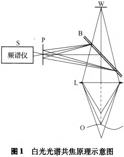
Confocal lenses of different specifications and sizes form different sizes of confocal spots, corresponding to different height measurement ranges throughout the entire white light spectrum area. Limited by factors such as spectral analyzers, the smallest confocal spot can reach the micrometer level, the highest longitudinal resolution can be several nanometers, and the measurement range is greater than 300μm, with the linear error generally reaching 0.1% (full scale).
3 Metal film thickness measurement system
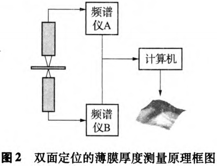
Self-supporting metal films have both their upper and lower working surfaces independently suspended in the air, not attached to any other substrate surface, so the measurement of their thickness must be achieved by using a dual-probe aiming and positioning method. Through the analysis of the technical principles of white light spectral confocal sensors, it is easy to achieve non-contact optical positioning and aiming of the sample surface. For the measurement of the thickness of self-supporting metal films, the dual-sided positioning aiming and thickness measurement can be realized by installing two sensors in a coaxial and symmetrically conjugate manner. As shown in Figure 2, the two spectrally confocal sensors installed in a symmetrically conjugate manner perform high-precision optical positioning of the upper and lower working surfaces of the metal film. The confocal signals from the two sensors are output separately and sent to the computer for processing, calculated according to specific algorithms, and the thickness measurement results are displayed. When the film sample is mounted on a two-dimensional scanning moving stage, the three-dimensional topography and total thickness variation (Total Thickness Value) of the entire film surface can be measured.
The total film thickness is calculated according to formula (1):

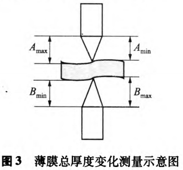
In the formula: Amax and Amin represent the maximum and minimum distances between the upper surface of the film and the upper sensor, respectively, while Bmax and Bmin represent the maximum and minimum distances between the lower surface of the film and the lower sensor, as shown in Figure 3. In actual measurements, apart from the upper and lower sensors needing to be adjusted to precise coaxial alignment, the initial axial positions require adjustment and calibration using a standard thickness block. Typically, a small-sized standard thin gauge block (such as 0.1 mm or 0.2 mm) is used for this purpose. In equation (1), Amin and Bmin correspond to the distances between the upper and lower surfaces of the standard gauge block and the upper and lower sensors, respectively, while Amax and Bmax correspond to the maximum distances between the upper and lower surfaces of the measured film sample and the upper and lower sensors, respectively.
4 Traceability of Measurement Values
In equation (1), the measurement result of the film thickness is directly related to the relative position of the sensors calibrated with a standard gauge block. The film thickness is obtained by comparing the measurement with the thickness of the standard gauge block. Therefore, in addition to the accuracy of the sensors, the accuracy of the standard gauge block will directly affect the measurement accuracy of the film thickness. The thickness measurement value of the entire measurement system can be directly traced back to the standard gauge block. The standard gauge block is one of the main standards for length measurement. High-level gauge blocks have very high accuracy. Therefore, using high-level gauge blocks to calibrate the film thickness measurement system can ensure the accuracy and traceability of the film thickness measurement system.
5 Analysis of Measurement Uncertainty
5.1 Mathematical Model

In the equation: T is the thickness of the measured film; Amaxp is the distance between the upper surface of the measured film and the upper sensor; Bmaxp is the distance between the upper surface of the standard block and the upper sensor; Aminp is the distance between the lower surface of the measured film and the lower sensor; Bmins is the distance between the lower surface of the standard block and the lower sensor. 5.2 Uncertainty influence components In equation (2),
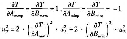
The uncertainty introduced by the upper and lower sensors is the same, so,
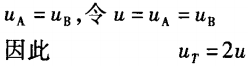
Among them, u is the standard uncertainty introduced by the sensor when aiming and measuring the surface of the film or gauge block.
5.3 Uncertainty Component Calculation
5.3.1 Measurement Repeatability S
After the system is calibrated with a secondary standard block, measurements are made on 5 thicknesses of 5μm, 10μm, 50μm, 100μm, and 270μm within the effective measurement range of the sensor, repeated 10 times under the same conditions, and the maximum experimental standard deviation does not exceed 0.10μm.
5.3.2 Uncertainty Component Introduced by Resolution
The system resolution is better than 0.01μm, and the resulting impact can be ignored.
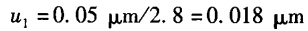
5.3.3 Uncertainty Component Introduced by the Standard Block Used for Calibration
u1 is the standard block used for calibrating the system, and its thickness measurement uncertainty is:
5.3.4 Standard uncertainty of sensor positioning and aiming measurement
The standard uncertainty of the upper and lower sensors aiming at the film or gauge block surface positioning measurement is mainly determined by the non-linear error of the sensor. The non-linear error of the sensor selected for this system is 0.1%, with a measurement range of 300μm; therefore.
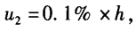
When the thickness is measured to be 300μm, u2=0.30μm
5.4 Combined standard uncertainty
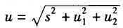
When the thickness is measured to be 300μm,

5.5 Expanded Uncertainty When measuring the thickness of a film at 300μm, taking the confidence factor k=2, then

When indicating relative uncertainty,
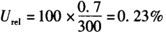
6 Measurement Comparison Test Analysis
The measurement of the total thickness of the film is completed by two sensors independently yet cooperatively, thus the measurement comparison test is divided into two aspects: the accuracy test of a single sensor measuring the standard step height and the accuracy test of dual sensors measuring the total thickness of the film.
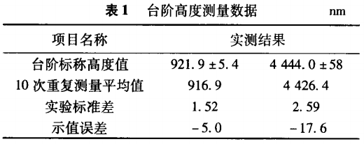
6.1 Accuracy Test of a Single Sensor Measuring Standard Step Height
Each sensor performs 10 repeated measurements on two different standard step heights, with the step height traceable to the laser wavelength standard. The measurement results are shown in Table 1.
6.2 Precision Test for Total Thickness
Measurement of Thin Films Using Dual Sensors
Before measuring the total thickness of the film, it is necessary to calibrate the axial and radial relative positions of the upper and lower sensors. The radial relative position is aligned using a small hole to ensure that the two sensors are precisely coaxial; the axial position is determined using a 1 mm Class II standard gauge block to establish the initial relative zero position of the upper and lower sensors. Then, measure the thickness differences of standard blocks with thicknesses of 5μm, 10μm, 50μm, 100μm, and 270μm, obtaining the measurement data shown in Table 2.
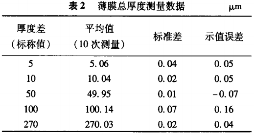
The calibration standard gauge blocks used can be directly traced back to the national primary standard gauge blocks. From the measurement results in Table 1 and Table 2, it can be seen that the technical performance of the single sensor is excellent, with very small errors at the two measurement points of 0.9 μm and 4.444μm; the film thickness measurement system composed of dual sensors not only has very good measurement repeatability but also ensures high measurement accuracy, verifying the correctness and reliability of the measurement system, fully meeting the requirements of uncertainty evaluation.
7 Summary
The metal film thickness measurement system with double-sided positioning and aiming built using white light spectral confocal sensors achieves the traceability of ultra-thin film thickness measurements to length base standards by comparing with standard gauge blocks, meeting the high-precision requirements for enhancing the measurement capability and value transfer of metal film thickness. It ideally achieves high-precision optical non-contact measurement of absolute thickness for ultra-thin films below 100 microns: repeatability is 0.79%, and the relative indication error is 0.99%. If measures such as constant temperature, vibration isolation, and anti-airflow disturbance are taken for the entire system, there will be significant room for improvement in measurement accuracy and stability.
This article is excerpted from the Journal of China Metrology, authored by Zhu Xiaoping, Du Hua, and Wang Weichen.


Recent Posts


Contact US
Product Information
Quantity
Unit
Piece
Support order samples, customization, wholesale direct, and complete payment. If the product you look for does not have corresponding customized content, pls fill out the form below to contact us, and we will reply ASAP.